![[Photo of the Author]](../../common/images/Guido-S.gif)
by Guido Socher (homepage)
About the author:
Guido likes Linux because it is a really good system to
develop your own hardware.
Content:
|
Part 2 -- A digital thermometer or talk I2C to your atmel microcontroller
![[Illustration]](../../common/images2/article369/title_369.jpg)
Abstract:
In this second part of the article we will connect a LCD display
and I will explain how the software works.
Those readers who are new to this series should first read
the first part (February2005
article365).
_________________ _________________ _________________
|
The new things
In the
previouse article
we build already most of the hardware and the main functionality
for temperature measurement and transmission of the data to a Linux
PC. In this article a LCD display and a very simple gtk GUI will be
added.
Adding these two things is very easy to do. I will therefore spend the rest of the article
to explain how the I2C software and the analog to digital converter
works.
The LCD display
For the LCD display we use a HD44780 compatible display as it was
already used in previous articles. These displays are very easy to use
in combination with microcontrollers because you can send them
ASCII characters.
As for all articles in this series you can again get all the parts
including the LCD display at shop.tuxgraphics.org
I use the same LCD driver code as in all previous articles. The files
which implement this LCD driver are lcd.c lcd.h and lcd_hw.h. They are
in the package which you can download at the end of this article.
The interface for this code is really easy to use:
// call this once:
// initialize LCD display, cursor off
lcd_init(LCD_DISP_ON);

// to write some text we first clear
// the display:
lcd_clrscr();
lcd_puts("Hello");
// go to the second line:
lcd_gotoxy(0,1);
lcd_puts("LCD");
How those HD44780 displays work is described in
the linuxfocus
September2002 article "Understanding HD44780 compatible LCD-displays"
The software is written such that it works with both 16x2 and 20x2 LCD displays.
 There is also an update to the circuit diagram. I discovered that some LCD
displays
have a higher capacitive load and lower resistance than others. This is probably
because they have a better ESD protection. This additional load can possibly cause
bit errors during the In Circuit Programming when the LCD display is connected to the SCK and MOSI pins.
There is also an update to the circuit diagram. I discovered that some LCD
displays
have a higher capacitive load and lower resistance than others. This is probably
because they have a better ESD protection. This additional load can possibly cause
bit errors during the In Circuit Programming when the LCD display is connected to the SCK and MOSI pins.
As a first solution I tried to connect additional resistors into the
lines to the LCD display. This worked for me but some people, especially laptop
users still had problems.
To avoid this problem all together I updated the circuit diagram and
the D7 and RS pins of the LCD display are now connected to PD7 and PD6.
It is not a problem to change this even if you have made the board already.
Just add a little wire under the board and cut the connection to PB3 with a
knife.
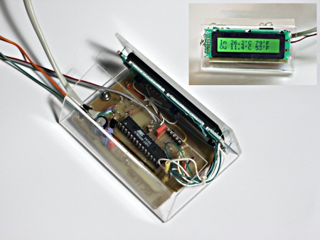
A little GUI
For those wo would like to have GUI on their desktop I made a really simple gui. It consists just of 2 labels which
are used to display the two line output of i2ctemp_linux command (the
i2ctemp_linux is the command which read the temperatures from the circuit via
I2C):

Now we have a really cool thermometer. With a lot of possibilities:
- You can read the temperature locally from the display
- You can have a little GUI on your desktop
- You can write values with a cronjob to a log file to get long term
statistics
I will now use the rest of this ariticle to explain a bit the internals
of the software.
How it works: Analog to digital conversion
The Atmega8 supports two modes. One where it permanently measures the analog
signals and
just triggers an interrupt when the measurement is ready. The application
software can then use this interrupt to quickly copy the result from
two registers into a variable.
The other mode is the so called single shot mode. Here only one conversion
is done. The single shot mode is still pretty fast. Including the setup time of the required
registers before and the reading out you can still get 100 conversion per
second. This is more than fast enough for us. So we use this mode.
On our Atmega8 we can use the analog input pins ADC0 to ADC3. In addition to
this there are the pins AGND (analog ground, connected to normal ground),
AREF (the reference voltage) and AVCC (connected to +5V).
During analog to digital conversion the analog signal is compared with
AREF. An analog signal equal to AREF corresponds to a digital
value of 1023. AREF can be any external reference between 0 and 5V.
Without the use of an external reference you can still do precise conversion
by either using an internal reference (2.56V) or AVCC. What is used is decided
in the software via the REFS0 and REFS1 bits in the ADMUX register.
The analog to digital converter can convert one of the input lines ADC0-ADC3 at
a time. Before you start conversion you have to set bits in the ADMUX register
to tell the chip which channel to use.
A simple analog to digital conversion would then look like this:
volatile static int analog_result;
volatile static unsigned char analog_busy;

analog_busy=1; // busy mark the ADC function
channel=0; // measure ADC0
// use internal 2.56V ref
outp((1<<REFS1)|(1<<REFS0)|(channel & 0x07),ADMUX);
outp((1<<ADEN)|(1<<ADIE)|(1<<ADIF)|(1<<ADPS2),ADCSR);
sbi(ADCSR,ADSC); // start conversion
Now the microcontroller will do the analog to digital conversion and
call the function SIGNAL(SIG_ADC) once it is ready. In this function we
can copy the result to a variable. As a programmer you must watch out
that you read the lower 8 bits first as the microcontroller has some locking
mechanism to simulate "atomic" reading.
SIGNAL(SIG_ADC) {
        unsigned char adlow,adhigh;
        adlow=inp(ADCL); /* read low first, two lines. Do not combine
                          the two lines into one C statement */
        adhigh=inp(ADCH);
        analog_result=(adhigh<<8)|(adlow & 0xFF);
        analog_busy=0;
}
After this we have the analog to digital conversion result available as
a number in the analog_result variable. This can the be used elsewhere in the
program. Very easy.
As for all interrupts you need to call sei(); to globally enable them. This
should be done somewhere in the main program (not shown above).
There were a lot if bits and flags which I will shorty explain:
- ADEN: Analog Digital Converter Enable, set this before setting ADSC
- ADIE: Enable ADC Interrupt (=enable calling of SIGNAL(SIG_ADC))
- ADIF: ADC Interrupt Flag (must be set to 1 before conversion)
- ADPS: ADC clock pre-scaler bits:
must be set such that the clock frequency divided by the
pre-scale factor is a value between 50 and 200 KHz.
The division factor is 2^ADPS (two to the power of the ADPS bits value).
The above setting (ADPS2=1, ADPS1=0, ADPS0=0 = decimal 4 -> 2^4 = 16 -> division factor = 16) is good for a clock frequency of
1MHz.
The Atmega8 has several possibilities for reference voltage selection. The
reference voltage is compared against our analog input voltage.
It is the voltage that corresponds to a digital value of 1023.
| REFS0=0, REFS1=0 | use external AREF, Internal Vref turned off |
| REFS0=0, REFS1=1 | AVCC with optional external capacitor at AREF pin |
| REFS0=1, REFS1=1 | Internal 2.56V Voltage Reference with (optional)
external capacitor at AREF pin |
An optional capacitor on the AREF pin can be used to suppress noise and
stabilize the AREF voltage.
How it works: I2C communication, Atmega8 part
I explained already in the part 1 (February2005 article365)
how this I2C protocol works. Let's now have a look at the software.
The Atmega8 has hardware support for I2C communication. Therefore you do
not actually need to implement the protocol. Instead you need to implement a
state machine. This tells the Atmega8 what to do next. Here is an example:
An I2C packet with our own slave address was received.
The Atmega8 will now call the function SIGNAL(SIG_2WIRE_SERIAL) with
the status code 0x60 (for other events we would get other codes).
--> We must now set a number of registers to tell the Atmega8 what to do next.
In this case we will tell it: receive the data part and acknowledge it.
When the actual data was received we will get called with status code 0x80.
--> Now we read the databyte and tell the Atmega8 to acknowledge the next data byte
if it comes.
When the communication is over we get a status code 0xA0 (stop condition) and we
can tell our application that a complete message was received.
The whole state machine for the I2C slave mode and all possible states are explained
in the datasheet
of the Atmega8 on page 183 (see link in reference section at the end of the
article).
Transmitting data is very similar. Have a look at the code!
How it works: I2C communication, Linux side
 First a word about the hardware. Even though I2C is a bus we only use
a point to point connection between one slave and the Linux PC as I2C master.
We can therefore save the pullup resistor as long as the slave can still
pull down the line without causing a short circuit. We just put a 4.7K resistor
into the line.
First a word about the hardware. Even though I2C is a bus we only use
a point to point connection between one slave and the Linux PC as I2C master.
We can therefore save the pullup resistor as long as the slave can still
pull down the line without causing a short circuit. We just put a 4.7K resistor
into the line.
The voltage levels
must be adjusted. This done with the Z-diode limiting the negative voltages
to -0.7V and the positive voltages to max +5.1.
After reading more about the internals of the Atmeag8 I came meanwhile
to the conclusion that the internal protection of the input stages of the
Atmeag8 is probably sufficient because the currents through the 4.7K resistor
are very low. We don't actually need the Z-diode.
It does however not harm to have the Z-diode.
The Linux I2C software implements basically a complete I2C stack. This is
because I wanted to have a little command line utility which does not
need any special library or kernel module. It should just work on its own.
If you look into the file i2c_m.c (see download) you can see that really every
I2C message is build bit by bit.
To generate the "bits" we must toggle the physical pins on the rc232 interface.
This is done with ioctl calls:
        // set RTS pin:
        int arg=TIOCM_RTS;
        ioctl(fd, TIOCMBIS, &arg);
... or to produce a zero:
        // clear RTS pin:
        int arg=TIOCM_RTS;
        ioctl(fd, TIOCMBIC, &arg);
If you want to port this stack to a different OS then you just change these
lines. The rest is plain C.
USB to RS232
For laptops which do these days not have a rs232 interface you can simply use
USB to rs232 adapter. I use e.g a no-name adapter which contains a Prolific 2303
chip.
The adapter which I have looks like this in the /proc/bus/usb/devices file:
Vendor=067b ProdID=2303 Rev= 2.02. See also "Use your ATEN
UC-232A USB adapter with Linux (Linuxfocus, November 2001, article 223)".
Conclusion
 I am now using the thermometer for 2 month and I really like it because you can
read it out directly on the display and you have the possibility to store all
the data on your PC. You can view it there, draw graphs do statistics. Really
cool.
I am now using the thermometer for 2 month and I really like it because you can
read it out directly on the display and you have the possibility to store all
the data on your PC. You can view it there, draw graphs do statistics. Really
cool.
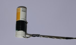
The outdoor sensor must be protected properly against rain (and sun). You can
try to wrap it into some plastic but I don't recommend this. No matter how
tight you tie it, water will eventually come in and stay in there. The NTC is quite robust and it
does not matter if it gets a bit humid as long as it can dry again.
Use a up-side down mounted tablet tube which you leave open at the bottom.
This way water will be able to get out again.
You can again order all parts (LCD display, PCB, microcontroller, ...) from
the tuxgraphics online shop: shop.tuxgraphics.org.
Have fun!
References
Talkback form for this article
Every article has its own talkback page. On this page you can submit a comment or look at comments from other readers:
2005-02-28, generated by lfparser version 2.52