![[Photo of the Author]](../../common/images/Guido-S.gif)
by Guido Socher (homepage)
About the author:
Guido likes Linux because it is a really good system to
develop your own hardware.
Content:
|
A digital thermometer or talk I2C to your atmel microcontroller
![[Illustration]](../../common/images2/article365/title_365.jpg)
Abstract:
The Atmega8 microcontroller from Atmel has plenty of digital
and analog input/output lines. It is the ideal device to
develop any kind of measurement equipment.
In this article we see how to interconnect the microcontroller
to a linux PC over a physical RS232 interface without the extra
MAX232 chip.
_________________ _________________ _________________
|
Introduction
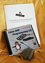
A pre-requisite for this article is that you have the GCC AVR
programming environment installed as described in my "Programming the AVR
microcontroller with GCC, libc 1.0.4" article. If
you want to avoid troubles with the installation you can of
course use the AVR programming CD from http://shop.tuxgraphics.org/
When you use such an advanced device as a microcontroller to
measure analog or digital signals then you want of course
interfaces to evaluate the data or send commands to the
microcontroller. In all the articles presented here in the past
we always used rs232 communication with the UART that is
included in the microcontroller. The problem is that this
requires an additional MAX232 chip and 4 extra capacitors.
Atmel suggests also that an external crystal osciallator is
required for the UART communication to work reliably. In any
case it is a lot of extra parts..... and we can avoid them!
The amount of data to transfer between PC and microcontroller
is usually very small (just a few bytes). Speed it therefore no
issue at all. This makes the I2C bus/protocol suitable for this
task.
I2C (prounouce "eye-square-see") is a two-wire bidirectional
communication interface. It was invented by Philips and they
have protected this name. This is why other manufacturers use a
different name for the same protocol. Atmel calls I2C "two wire
interface" (TWI).
Many of you might already be using I2C on their PCs without
knowing it. All modern motherboards have an I2C bus to read
temperatures, fan speed, information about available memory....
all kind of hardware information. This I2C bus is unfortunately
not available on the outside of the PC (there is no physical
connector). Therefore we will have to invent something new.
But let's first see how the "two wire interface" (=TWI =
alternative name for I2C) works.
How I2C/TWI works
The datasheet of the Atmega8 (see references) has actually a
very detailed description starting on page 160. I will therefore
present here just an overview. After this overview you will be
able to understand the description in the datasheet.
On the I2C bus you always have one master and one or several
slave devices. The master is the device that initiates the
communication and controls the clock. The two wires of this bus
are called SDA (data line) and SCL (clock line). Each of the
devices on the bus must be powered independently (same as with
traditional rs232 communication). The two lines of the bus are
normally connected via 4.7K pullup resistors to logically
"High" (+5V for 5V ICs). This gives an electrical "or"
connection between all the devices. A device just puls a line
to GND when it wants to transmit a 0 or leaves it "High" when
it sends a 1.
The master starts a communication by sending a pattern called
"start condition" and then addresses the device it wants to
talk to. Each device on the bus has a 7 bit unique address.
After that the master sends a bit which indicates if it wants
to read or write data. The slave will now acknowledge that it
has understood the master by sending an ack-bit. In other words
we have now seen 9 bits of data on the bus (7 address bits +
read_bit + ack-bit):
| start | 7-bit slave adr | read_data bit | wait for ack | ... data comes here
What's next?
Next we can receive or transmit data. Data is always a multiple
of 8 bits (1 byte) and must be acknowledged by an ack-bit. In
other words we will always see 9-bit packets on the bus. When
the communication is over then the master must transmit a "stop
condition". In other words the master must know how much data
will come when it reads data from a slave. This is however not
a problem since you can transmit this information inside the
user protocol. We will e.g use the zero byte at the end of a
string to indicate that there is no more data.
The data on the SDA wire is valid while the SCL is 1. Like
this:
SDA H -\       /---\     /---\          /---\
    L   \-----/     \---/     \--------/     \------....

SCL H ----\     /-\       /-\     /-\    /-\    /-\
    L      \---/   \-----/   \---/   \--/   \--/   \-....


  | START |      1 |       1 |     0 |    1 |    0 |
One of the best things about this protocol is that you do not
need a precise and synchronous clock signal. The protocol does
still work when there is a little bit jitter in the clock
signal.
Exactly this property makes it possible to implement the I2C
protocol in a user space application without the need for a
kernel driver or special hardware (like a UART). Cool isn't it?
The plan
As said before we cannot use the PCs internal I2C bus but we
can use any external interface where we can send and receive
individual data bits. We will just use the RS232 hardware
interface of our PC. In other words our communication interface
is still the same as in previous articles but we save the
MAX232 hardware, capacitors, etc...
The tough part is of course to implement the I2C protocol from
scratch. It took me 5 weeks to learn it and debug it but now it
is done and you can just copy it :-). I hope you remember the
value of this code when you use it.
As an example application we will build a thermometer. You can
of course measure something else or just switch on/off lights.
It's up to you.
In a second article we will add a local LCD display. In other
words you will have a thermometer where you can read the
temperature directly from the display and/or you can read it
out with your linux PC. The display comes in a second article
in order not to overload this one.
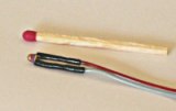
NTCs are small, cheap and accurate enough |
The temperature sensor
It is possible to get already calibrated temperature sensors
(some of which talk I2C ;-) but they are quite expensive. NTCs
are cheaper and almost as good even without individual
calibration. If you calibrate them a bit then it is
possible to achieve accuracy behind the decimal point.
One problem with NTCs is that they are non linear. It is
however just a matter of semiconductor physics to find the
right formula to correct the non linear curve. The
microcontroller is a little computer therefore mathematical
operations are not a problem. NTCs are temperature dependent resistors. The
value R of the NTC at a given temperature is:
 T or Tc is the temperature value that we are looking for. Rn is
the resistive value of the NTC at 25'C. You can buy 4k7, 10K,
... NTCs so Rn is this value.
T or Tc is the temperature value that we are looking for. Rn is
the resistive value of the NTC at 25'C. You can buy 4k7, 10K,
... NTCs so Rn is this value.
The circuit
Circuit diagram. Click on the diagram for a more
detailed view.
|
Now we have all we need to build a digital thermometer. We add
two NTC sensors, one for inside temperature and one for outside.
You can add more if you want (conn3, pin PC2 is e.g free). In
the circuit diagram I add already the needed wires for the
connection of an LCD display because I don't want you to build
a complete new circuit for the next article.
There is also an LED connected. It does not cost much and is
really useful for basic debugging. I used it e.g to debug the
I2C state machine when I developed the I2C communication
between PC and microcontroller. During normal operation we can
just leave it blinking to indicate that measurements are taken.
The circuit is otherwise straight forward. The analog to
digital converter in the microcontroller is used to measure the
voltage on the NTC which will then be converted into a
temperature value.
The Atmega8 has two options on what is used as a reference
voltage for the analog to digital converter. It can use either
the 5V (AVcc) or an internal 2.56V reference. For the inside
temperatures we will not need a temperature range which is as
big as for the outside sensor. +10'C to +40'C should normally
be sufficient. We can therefore use the 2.56V reference when we
measure the indoor sensor. This gives very high accuracy as the
1024 possible digital values are then spread over only 0-2.56V
that is we get a resolution of 2.5mV (more accurate than most
digital voltmeters!).
The CD-pin on the RS232 is an input line and it is connected to
SDA on the I2C bus. We use it to read data from the
microcontroller. DTR and RTS are output lines. When the PC puts
data-bits on the SDA line then it just toggles DTR. The
I2C-master (here the linux PC) controls the SCL (clock) line.
In other words the clock line is an output line on the rs232.
The 78L05 is used to generate a stable power supply and
reference voltage. You can use almost any type of power supply AC
or DC between 7.5V and 12V. 9V is a good choice.
Making the board
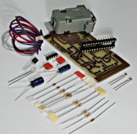
tuxgraphics.org sells all the parts needed for this article
together with a properly etched board. |
You can of course re-use the prototyping board which we used in
the previous article. Just re-connect the LED to pin 11 and add
all new things.
If you want to have a nice and good looking circuit then it
makes sense to use a new board. Because the circuit is much more
complicated it makes a lot of sence to properly etch a printed
circuit board. After reading Iznogood's linuxfocus article on
gEDA I decided to also use gEDA instead of Eagle. gschem the
schematic drawing tool for gEDA is very good. It does not have
a library of symbols as big as Eagle and I had to create the
symbol for the Atmega8 but it is very easy to use and as good
as Eagle. Quite a bit more problematic is pcb, the tool to draw
PCBs. When you come from Eagle you will first of all notice
that it is possible to disconnect the parts from the rubber
bands. To be sure that the right rubber band is connected to
the right pin you have to run
Connects->Optimize rats-nest once in a while. You should first complete the
circuit diagram and then make the board. Annotation between the
two is only manual. 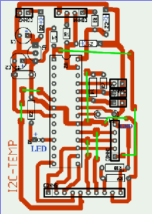
I used the orange colored layer for drawing. Somehow the other
layers would not generate any output when printing. The problem
is that the orange colored layer is acutally on the side of the
board where the parts are. If you write text in this layer then
it has to be mirrord when you print it on the physical board.
Therefore I made the basic layout with pcb and all the rest
with gimp.
Thanks to shop.tuxgraphics.org you will
not have to deal with hazardous chemicals and run around town to
find the right components. They sell all the parts needed for
this article. This way you can concentrate on the fun part and
successfully assemble this circuit.
Putting everything together
When you assemble the circuit then pay attention to the parts
where polarity is important: Electrolyte capactitors, the
diode, Z-diodes, 78L05, LED and the microcontroller.
Before you put the microcontroller into the socket you should
verify the power supply part. If this does not work you will
not only get incorrect temperature readings but you may also
destroy the microcontroller. Therefore connect external power
(e.g a 9V battery) and verify with a voltmeter that you get
exactly 5V on the socket pin of the microcontroller. As a next
step connect the circuit to the rs232 port of your linux PC and
run the porgram i2c_rs232_pintest with various combinations of
signals.
i2c_rs232_pintest -d 1 -c 1
i2c_rs232_pintest -d 0 -c 1
i2c_rs232_pintest -d 1 -c 0
This program sets the voltage levels on the RTS (used as SCL,
option -c) and DTR (used as SDA, option -d) pins of the rs232
port. The rs232 port has voltage levels of about +/- 10V.
Behind the Z-diode you should however measure only -0.7 for a
logical zero and +4-5V for a logical one.
Insert the microcontroller only after your circuit has passed
the above tests.
Using the I2C communication
Download (see references) the linuxI2Ctemp tar.gz file and
unpack it. The I2C communication is implemented in 2 files:
i2c_avr.c -- the i2c statemachine for the atmega8
i2c_m.c   -- the complete i2c protocol on the linux side
I have given the atmega8 the slave address "3". To send the
string "hello" to the atmega8 you would execute the following C
functions:
address_slave(3,0); // tell the slave that we will send something
i2c_tx_string("hello");
i2cstop(); // release the i2c bus

on the microcontroller side you would receive this "hello" string with
i2c_get_received_data(rec_buf);
Very easy. Reading data from the microcontroller is similar.
Look at the file i2ctemp_avr_main.c to see how it works when
the temperature readings are done.
How warm is it?
To compile and load the code for the microcontroller run the
following commands from the linuxI2Ctemp package directory.
make
make load
Compile the two programs i2c_rs232_pintest and i2ctemp_linux
make i2c_rs232_pintest
make i2ctemp_linux
... or just use the pre-compiled versions in the "bin"
subdirectory.
To read temperatures simply run:
i2ctemp_linux
... and it will print indoor and outdoor temperatures. To make
this data available on a website I suggest to not directly run
i2ctemp_linux from the webserver because the i2c communication
is very slow. Instead run it from a cron job and write from
there to a html file. An example script is included in the
README file of the linuxI2Ctemp package.
Conclusion
The I2C protocol requires very little extra hardware and is
optimized for transmitting or receiving small amounts of data.
That is exactly what we need when we want to communicate with
our own microcontroller hardware. It is really a very nice
solution!
In this article I have focused very much on the hardware part.
If you like this article then I will also write a second one
where I describe how the software works. Especially how to do
analog to digital conversion and how the I2C protocol
implementation works. In this next article we can also add an
LCD display and add conversion between Farenheit and Celsius.
References
Talkback form for this article
Every article has its own talkback page. On this page you can submit a comment or look at comments from other readers:
2005-02-03, generated by lfparser version 2.52