![[Photo of the Author]](../../common/images/Guido-S.gif)
by Guido Socher (homepage)
About the author:
Guido likes Linux because it is a paradise for people who
want to develop their own software and hardware.
Content:
|
Linux USB LCD display with watchdog and buttons
![[Illustration]](../../common/images/article286/linuxusblcd_title.jpg)
Abstract:
This article is the result of the very positive feedback on the
hardware articles that I have written so far. You LinuxFocus readers
are really a great audience! Some of you wanted to know how to
interface the USB bus. So here is a nice solution. We use the
LCD display from the May
2002 article and make it work with the USB bus. The whole
thing will be powered from the USB bus. Therefore you do not
need any extra power supply.
For this article you need at least a partial installation of
the Linux AVR development environment. How to set it up is
described in this article: Programming the AVR
Microcontroller with GCC.
_________________ _________________ _________________
|
Introduction
USB is cool because it is a modern interface and it offers the
possibility to power the devices directly via the USB bus. The
connectors are small and high volumes of data can be
transported over a small cable. That's the positive things
about USB. The down side is that hardware design is difficult
due the high frequencies and the protocol is rather complex.
Just take a look a the specifications (http://www.usb.org/developers/,
you want the 1.1 specification) and you will be shocked. It's
327 pages long and very difficult to understand. No wonder that
there are soooo many faulty implementations of USB devices. A
more user friendly introduction can be found at http://www.beyondlogic.org/
but the specification is still complex.
What to do? How can we interface our Microcontroller to the USB
bus? FTDI, a Scottish company, has the solution (http://www.ftdichip.com). They
offer a chip which implements a USB
serial interface. One side of the FT232BM chip is rs232 and the
other USB. In other words you just replace the MAX232 which you
previously needed for the power conversion on the rs232 lines
with this FT232BM chip and you are done.
The driver
The FT232BM is a true cross platform solution. Drivers are
available for multiple operating systems. The Linux kernel
module is called ftdi_sio and is open source. It is part of the
standard Linux kernel. The FT232BM offers more than just a USB
to rs232 conversion and the Linux kernel module is still under
development to implement all functions. The USB to rs232 is
however ready and I was e.g able to use a standard Redhat 7.3
Kernel (2.4.18) without recompilation or any modification. Just
plug it in.
ftdi_sio is being developed at http://ftdi-usb-sio.sourceforge.net/.
With my Redhat 7.3 all modules would load automatically when I
plug in the USB connector. If it does not work for your Linux
distribution then check that you have the following modules
(for USB-UHCI):
/sbin/lsmod usb-uhci
/sbin/lsmod usbcore
/sbin/lsmod usbserial
/sbin/lsmod ftdi_sio
The device file to communicate with the hardware is
/dev/ttyUSB0
The developers of ftdi_sio recommend at least Kernel 2.4.20 but as
you can see 2.4.18 does also work (at least the for the functions we
need here).
The schematic
The circuit is straight forward. You just insert the FT232BM
between the Rx/Tx lines of the Microcontroller and the USB
connector. A 6 Mhz Crystal and some other parts are needed
which are described in the design specification from FTDI. The
ferrite bead (in the schematic on the right) is a little coil
which filters high frequencies (the USB bus runs at 48Mhz). You
can also wind 10 loops of a thin wire over a 1K resistor and
use it as a coil.
One thing to pay attention to is the power consumption. You
must consume less than 100mA if you design a bus powered device.
In addition your device
must support USB suspend mode. When the pin named "sleep" on
the FT232BM goes low then the device must consume less than
0.5mA. The latter is a very tough requirement to implement. The AVR supports
an "idle mode" where it consumes less than 2mA and a "power
down" mode where it consumes only 20uA. It seems however easier
to wake up the Microcontroller from "idle mode". I have
therefore decided to use "idle mode" even if this violates the
USB specification a little bit. The optional background light of
the display will be switched off and the whole circuit will
then consume 3mA. 3mA is more than 0.5mA but the USB host
controller chips can not measure the current so accurate that
they will detect this. It should work.
Having said all this I must admit that I don't have a computer
which supports suspend. Therefore I could not test this part.
If you have a computer, probably a modern Laptop, that supports
suspend then please test this and let me know what the result
is.
The rest of the circuit is almost identical to the one
presented in the May 2002
article. I will therefore not explain any further details.
You can click on the schematic for a bigger picture. The eagle
files are packed together with software. You can download it at
the end of the article.
The board is single sided and only the blue layer should be
etched. The red lines are wires.
The USB Type-B connector which you need for this circuit has
the following pinout:
Working with SMD chips
SMD chips have good mechanical and electrical properties but
they are a nightmare for hobby electronic fans. You really need
some soldering skills and at least the part of the board where
the SMD chip is mounted must be etched very clean and with high
quality. In other words this is nothing for beginners. Look at
the alternatives below if you are not sure that you can etch
the board and solder the chip.
Solder the SMD chip to the board before you add any other
parts.
To solder the chip on put a little bit of solder onto the pads
where the SMD chip goes. Next put a thin film of SMD solder
paste (some people call it solder honey because it looks like
honey). There is also a German company called "Kontakt Chemie"
which produces a varnish called "Lötlack" spray. You can
use this "Lötlack" spray instead of the solder honey if
you want.
Clean your soldering iron. There must not be any solder left on
the tip of the iron. Then position the FT232BM exactly. Gently
press on every pin of the chip with the soldering iron. Do not
add extra solder. 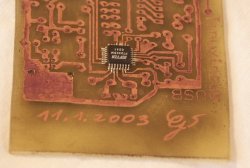
This procedure works very well. It is not important that you
have a small soldering iron. Just use an ordinary one and make
sure that it is clean before you touch the pins of the chip. I
don't recommend to use kitchen toasters or other crude methods.
You are likely to damage the chip with any other method.
The test
I suggest testing the circuit in two steps. First connect the
circuit without the AVR Microcontroller in the socket. Linux
should recognize in FTDI chip and you should see the following
entry in /proc/bus/usb/devices:
T: Bus=02 Lev=01 Prnt=01 Port=00 Cnt=01 Dev#= 2
Spd=12 MxCh= 0
D: Ver= 1.10 Cls=00(>ifc ) Sub=00 Prot=00 MxPS= 8 #Cfgs=
1
P: Vendor=0403 ProdID=6001 Rev= 2.00
S: Manufacturer=FTDI
S: Product=USB <-> Serial
C:* #Ifs= 1 Cfg#= 1 Atr=80 MxPwr= 90mA
I: If#= 0 Alt= 0 #EPs= 2 Cls=ff(vend.) Sub=ff Prot=ff
Driver=serial
E: Ad=81(I) Atr=02(Bulk) MxPS= 64 Ivl= 0ms
E: Ad=02(O) Atr=02(Bulk) MxPS= 64 Ivl= 0ms
After that insert the AVR Microcontroller and load a test program
which will cause the LED to blink. Unpack the linuxusblcd
software package (see download at the end of the article) and
type:
make testload0
The programmer cable and the USB connector must both be plugged
in.
If this test works then you can be sure that the Microcontroller
will work.
After this you can load the complete software into the
Microcontroller:
make load
Now you can use "ttydevinit /dev/ttyUSB0" to initialize the usb
serial connection and with "cat > /dev/ttyUSB0" you can
"talk" to the circuit.
ttydevinit /dev/ttyUSB0
cat > /dev/ttyUSB0
D=hello world
This will write "hello world" on the display. See the May 2002
article for details. The code for the May 2002 article
also contained a program called llp.pl which can be used to
have an interactive dialog with your computer via the 2 buttons
on the LCD display. You can re-use it here.
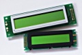
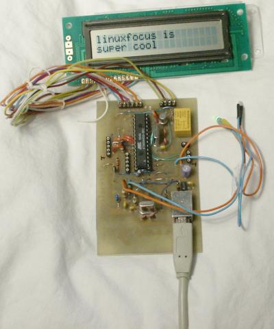
... and here is the working display (buttons were not connected
when the picture was taken,
the FT232BM is under the board):
Alternatives
Although the circuit presented here is very simple it is still
nothing for beginners because of the skills you need to solder
on the SMD chip. Therefore consider a ready made commercial
solution of you don't feel confident about the SMD chip. The
disadvantage is that you normally don't get all the extras like watch
dog, LEDs and buttons. You usually get only the LCD display.
The prices for the ready made commercial USB displays are
reasonable. The parts alone for this article cost about 30 EUR
and ready made displays are in the same order.
Unfortunately most of the commercial products use own vendor
IDs even if they are based on the ftdi chip. This means that
the kernel module will not recognize them because the USB driver
depends on these numbers. You need to edit the kernel sources
and re-compile. Future kernel versions may already work if
somebody else has updated the code.
- http://www.matrixorbital.com/ They use also the ftdi
232bm but with their own vendor IDs. The display is called
LK202-24-USB.
- http://www.usblcd.de/ This solution has it's own kernel
module. It is however part of the standard Linux kernel. It
will work out of the box with any 2.4.x kernel. Probably a very good
solution.
- http://crystalfontz.com/ Their usb displays (632 and 634)
use the FT232AM with own product IDs.
- http://www.cwlinux.com/eng/products/products_lcd.php I discovered this
site just recently. They see to have LCDs with keypads. It's however
twice as expensive as the solution from this article.
References
Talkback form for this article
Every article has its own talkback page. On this page you can submit a comment or look at comments from other readers:
2005-02-11, generated by lfparser version 2.52