| This document is available in: English Castellano Deutsch Francais Italiano Nederlands Turkce |
![[Photo of the Author]](../../common/images/Ismael-R.gif)
by Ismael Ripoll & Elisa Acosta About the author: Ismael Ripoll, Ph.D. from the Polytechnic University of Valencia in 1996. Professor in operating systems at the Department of DISCA. Research interests include real-time scheduling and operating systems. Linux user since 1994. Hobbies: Trekking through the Pyrenees mountains, skiing, and home electronics. Elisa Acosta is a Computer Engineer in the Polytechnic School of Valencia. At the moment she works for Indra (a communication firm) on year 1900 problems :-) This article is based on what Elisa Acosta did in her final year project. Content: |
![[Illustration]](../../common/images/illustration33.gif)
Abstract:
Using a simple electric circuit, we can make RT-Linux receive orders from an infra-red remote control.
You don't need electronic and hardware knowledge, to understand this article even though we will be talking about a small hardware component used for the Infra-red Remote Control.
A project called "lirc" (Linux Infra-red Remote Control) was initiated by Ralph J. K. Metzler (http://fsinfo.cs.uni-sb.de/~columbus/lirc/) for which an infra-red receptor driver was developed using Linux "normal"services. With "normal" I mean it didn't use RT-Linux real time extensions. In this article we start with the same subject, but look at solutions based on RT-Linux.
In the first part of our project we look at the hardware needed to connect the infra-red receptor and the computer. In the second part we see how we can evaluate the signals from the infra-red receptor using Real-Time Linux. We only need a minimum of hardware : a Sharp (IS1U60) infra-red receptor and a few cables and connectors.
The IS1U60 infra-red receptor is an electronic marvel; within a three pins plug (two for power and one for ground) it's able to do almost all of the reception and conversion work, providing a TTL serial signal on the third pin.
PCs have a lot of connectors to plug every type of digital peripherals (modems, printers, SCSI, keyboard, monitors, etc...), but nothing that allows us to connect it to simple electronic items. In other words, a standard PC doesn't have a data acquisition card. A card with witch you would be able to read the voltage of a specific line.
By chance, the parallel port (as well as the serial port) can be used as a generic in/out port. Many peripherals use this feature to communicate with the PC, such as e.g Iomega ZIP drive.
We will use the parallel port to receive data from the infra-red receptor. We will only need one pin of the parallel port, since the infra-red receptor only has a single data pin.
As already mentioned, the IS1U60 is an infra-red receptor especially designed to make receptors for domestic appliances.
The remote control signal is really complex, since different types of codification and modulation are combined. Let's observe this signal.
The physical media carrying the remote control signal is a light wave in the the spectrum of the infra-red. This kind of light is absolutely harmless unlike ultraviolet light. The infra-red light is invisible to human eye but not to semiconductors dispositives. The infra-red light sources are: the sun, the incandescent bulbs, LED diodes, etc. A infra-red LED is used by remote control to emit the signal.
| Infra-red light | Visible | ultraviolet light |
|
|
||
Every semiconductor dispositive is light sensitive (any color/frequency). Most semiconductors are therefore packaged in black plastic to protect them from the light. An infra-red sensor is basically made of a semiconductor diode, with a glass on top only letting the infra-red light go through.
An infra-red sensor built this way, will be able to detect any infra-red light, whatever source is generating it. Remote control designers had to add an encoding feature to the light emitted from a remote control to make it distinct from the rest of light sources. The signal emitted from a remote control is modulated at frequencies between 32 and 40 Khz, this depends a bit on manufacture and model. Let's assume the remote control frequency is 38 Khz, since it's the most common value. More than 90% of the devices use this frequency or a very close one.
|
| The infra-red receptor. |
We must keep in mind that everything done to emit the signal, will have to be removed during reception. If we emit an infra-red light, we need to receive it; if this signal is modulated with a 38 Khz carrier, then this carrier has to be eliminated (filtered). The demodulation is done in analog way with a single band pass frequency filter (to eliminate every frequency far from the emission frequency) and a rectifier/integral filter.
The infra-red light modulated at 38Khz, is the communication media used between the emitter (remote control) and the receptor (TV, video, etc.). Now we must determine how the information is transmitted, that is to say, which bits identify the pressed key on the remote control.
The encoding of the information depends on the manufacture, but fortunately, in this project we don't need to know these methods, we just have to compare them.
Considering the modulation of the signal it is obvious that the information is transmitted in series. One bit after the other and accordingly we only need one data stream on the receiving side.
The following comes from the sensor IS1U60 technical specifications (http://ns14.sharp.co.jp/ecg/unit/is1u60/is1u60-fea.html), and presents the internal structure. The two left arrows represent the infra-red light converted into an electric signal through the led. The signal is amplified, the direct component is eliminated, it's filtered to let frequencies close to 38 Khz go through, next it's corrected (demodulator+integrator), and last it's converted into a compatible TTL signal.
The parallel port is designed to communicate with printers, but over time, and because there was nothing similar available on PCs, it was used to connect all kind of peripherals.
At the moment, there are at least two variations (ECP, EPP) to transform the parallel port into a true generic communication port. Our project is rather modest concerning the functions required from the parallel port, hence any version will be usable. As a matter of fact, we only need one IN stream.
|
| Detail of state register |
The PC controls the parallel port with three 8-bit registers. There are a data register (0x378), a state register (0x379) and a control one (0x37A). The values in parenthesis represent the usual registers addresses of the first parallel port.
Writing into the control register allows us to program the port. From the 8 bits of the register, only bit 4 is used. Writing a "1" into this bit causes the port hardware to generate an interrupt (usually number 7) when it detects the ACK state stream going from high level (5 volts) to low level (0 volt).
The data register is an open door to the pins of the connector. Every data we write into this port will appear in pins 2 to 9 of the parallel connector. This port only is an OUT port. Since we must read the values the infra-red receptor provides, this port is useless for us. We need an Input port.
The state port informs about the state of the printer control line. From these lines the printer is able to inform the computer about its state. These line are managed by the printer (or an external device) and the computer reads them, accordingly they are IN lines. Even if it is an 8-bit register, only the 5 most significant bits are bound to the lines, the other three bits are always zero. The line numbers are named after the functionality they have when communicating with a printer, but these lines are in fact generic digital lines you can use for almost anything.
Among these 5 lines, the most interesting is the pin 10 (bit 6 of the register), since it is used as a digital entry line, but it can as well produce interruptions when the state of the line changes (from 5 to 0), as mentioned above.
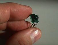
|
| Physical description of chip and binding |
The infra-red receptor needs between 4.7 and 5.3 volts. If the voltage goes lower than 4.7, then receptor stops working. This power supply voltage can be obtained in different ways:
Using batteries. In this case it's better to use a 4V5 battery in series with a small (or old) 1V5 battery. The resulting voltage won't be 6V but 5.5V because the small 1V5 battery not provide full power.
Using a regulated power supply source (device converting alternating current into direct current of low voltage). Even if it's simple to build, it's beyond the scope of this article. You can buy such a general purpose power supply in the same shops where you buy electronic devices.
Getting the 5 volts from the computer. In a computer, there are two types of cable: flat cables (carrying the data) and thick red, black and yellow cables for power supply. The red cable is the +5V and the black one is the ground or 0V.
To supply power to the receptor, we will connect the black cable to pin 2 of the receptor and the red one (5V) to pin 3.
The connection to the parallel port is as simple as connecting the receptor pin number one to pin 10 of the parallel port and the receptor pin 2 to pin 18 of the parallel port. Note the pin GND (ground) must be connected in two places: power supply ground and parallel port ground.
To make these connections you can use any type of cable.
| REAL-TIME module |
|---|
#define PERIOD 100
#define SIZE 8192
#define FIFO_ZERO 0
#define LP0 0x378 /*Address /dev/lp0*/
#define STS LP0+1

RT_TASK task;

//---------- Real time task
void Real_Time_Task(){
  unsigned short data1, data2=0;
  unsigned long  cont = 0L;

  while(1){
    // Read the port value
    data1=inb(STS) & 0x40;

    // If no change..
    if ( data2 == data1) {
      // Increment the counter.
      cont++;
    } else {

      // Send the counter value.
      rtf_put(FIFO_ZERO,
              (char *) &cont,
	    sizeof(cont));
      cont = 0L;
      data2 = data1;

    }
    rt_task_wait();
  }
}

//------------- Main program
int init_module(){
  RTIME now = rt_get_time();

  // Create communication FIFO with Linux.
  rtf_create(FIFO_ZERO,SIZE);

  // Create the real time task.
  rt_task_init(&task,Real_Time_Task,1,3000,4);

  // Make it periodic.
  rt_task_make_periodic(&task,now+3000,PERIOD);

  return 0;  // Everything worked.
}

//------------- To unload the module
void cleanup_module(){
  rt_task_delete(&task);
  rtf_destroy(FIFO_ZERO);
}
|
The simplest way of measuring the state of the parallel port ACK pin is to create a periodic task reading the bit state (pin). If it detects a change, while the pin keeps the same state, we increment a counter. This way the counter ticks are representing the time during which the bit stayed at the same level. If we detect a value change, then we send the counter value to a normal Linux user task via a FIFO. A Linux process must be waiting for FIFO reading. The read values are equivalent to the signal time at low level and then at high level.
It's fundamental to get an accurate measurement of the signal given by the receptor, as a matter of fact, it's the only reason for using a real time system. Interpreting the sequence of values given by the real time task to identify the pressed key has no time restriction and it can be managed within a Linux normal process.
Another way of measuring changes in the ACK pin is to install an interruption manager on interrupt 7. With this solution you don't need to use a planifier or a periodic task.
The function init_module launches the task. You just have to create the communication FIFO for the task, to create the task and last to convert it into a periodic one. The period value (100 RT-Ticks, which is about 90 micro seconds) is given for testing and error management. The shorter the period the higher the resolution of our measurement, but a tight loop with short periods consumes more CPU power.
The following user program sends to the standard output what it reads from the device /dev/rtf0. With this simple program, we can "see" the form of each frame sent from the infra-red emitter when a key is pressed.
| User program |
|---|
#include |
The value 700 appearing in the program is an estimated value and represents the minimum amount of time between two consecutive frames.
Although most of the remote controller use a similar infra-red signal, the encoding of the keys can be different. To recognize the pressed key is a problem of "form recognition" and not a "real time" one. The best way to make a program recognizing a concrete command is to watch the output of this program and get an an idea on how our remote control emits the data.
In simplified terms, we can say when a remote control key is pressed, it sends a typing sequence which we see on the screen as numbers sequence. If we hold the key pressed, the command will send the same sequence in a periodic way (SONY remote controls are the exception).
Let's watch it (you have to remember to install the needed real time modules: FIFO and planifier):
  # modprobe rt_fifo_new
  # modprobe rt_prio_sched
  # insmod ir
  # ir_get
  0
  126509 13 6 23 7 13 7 12 7 12 7 12 7 12 8 11 8 11 8 11 8 11 8 11 19 11
  1081 13 6 23 7 12 7 12 8 11 8 11 8 11 8 12 7 12 8 11 8 11 8 11 19 11
  1080 14 6 23 7 12 7 12 7 12 7 12 8 11 8 11 8 11 9 11 7 12 8 11 19 11
  1080 13 6 24 6 13 7 12 7 12 7 12 7 12 7 12 8 11 8 11 8 11 8 11 19 11
We can observe that this command repeats the same sequence when the key is pressed down. The other thing to note is the measurement error. The figures of the different frames only have a variation of 1, this represents the quantification error.
To program a recognition software, you only have to keep in an array each frame sent from the command, and then, each time a frame arrives, you compare (accepting a + or - 1 error) with the ones you have in the array of frames. This program is left as an exercise to the reader.
Some remote controls emit a distinct frame each time a key is pressed, even if we press always the same one. Here is what they do: when we press a key, they send a frame we call "FrameA", if we release and press the key again, they emit "FrameB" on the next press they emit again "FrameA" and so on. If we maintain the key pressed, the same frame is emitted various times. This way, the receptor can see the difference between a long press and two successive press. How do you think the key sequence 1 1 (eleven) is managed on new remote controls?
|
|
Webpages maintained by the LinuxFocus Editor team
© Ismael Ripoll & Elisa Acosta, FDL LinuxFocus.org Click here to report a fault or send a comment to LinuxFocus |
Translation information:
|
2001-01-27, generated by lfparser version 2.8